

- Stock: In Stock
- Brand: Others
- Model: IR-SENSOR-001
- Weight: 50.00g
- SKU: IR-SENSOR-001
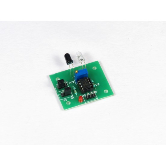
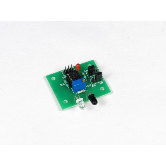
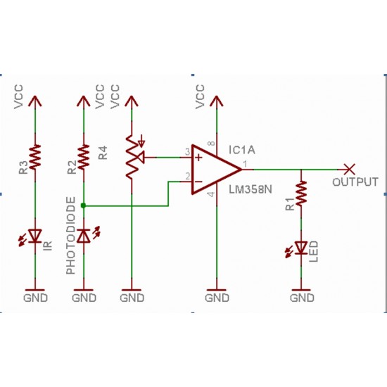
This IR PROXIMITY/ OBSTACLE SENSOR is designed to work with almost all ARDUINO boards and MICROCONTROLLERs - AVR, PIC, 8051, etc
- Operating Voltage: 5V
- MODE SELECTION - Configurable HIGH / LOW Output State (Using AH and AL pins)
- Adjustable Range using preset (potentiometer on board)
Since the sensor module works on INFRARED, for obstacles with reflective surfaces (white colored), the maximum range will be higher and for non-reflective surfaces (black colored), the maximum range will be lower. This can in turn be used for detecting white/black lines (in line follower ROBOTs) or bright/dark objects (in object identification ROBOTs)
Useful for various Robotic Applications, Room Visitor Counter Systems, etc
Modes of Operation
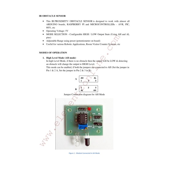
1. High Level Mode (AH mode)
In High Level Mode, if there is no obstacle then the output will be LOW (0V) & detecting an obstacle will change the output to HIGH (5V) Level.
This mode can be enabled, if both the jumpers are connected to AH (Set the jumper A on Pin 1 & 2, Set the jumper B on Pin 2 & 3).
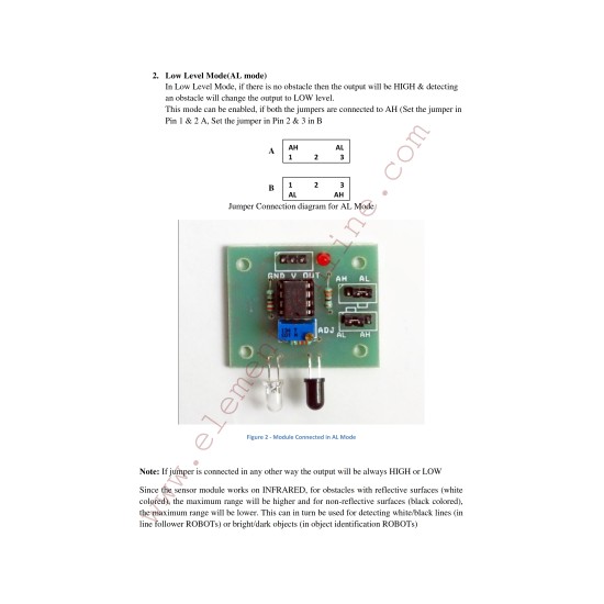
2. Low Level Mode (AL mode)
In Low Level Mode, if there is no obstacle then the output will be HIGH (5V) & detecting an obstacle will change the output to LOW (0V) level.
This mode can be enabled, if both the jumpers are connected to AL (Set the jumper A on Pin 2 & 3, Set the jumper B on Pin 1 & 2).
Note: If jumper is connected in any other way the output will be always HIGH or LOW


