


 Development Board using Arduino IDE")
STM-32 development board is equipped with a 32-bit and ARM Cortex M3 Architecture making it powerful enough to handle industrial needs. The most important feature that makes it the favourite of engineers world-wide is its ability to be programmed by the Arduino IDE itself.
In this blog we will look into the basics about the STM32 development board and blink an LED using the same.
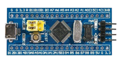
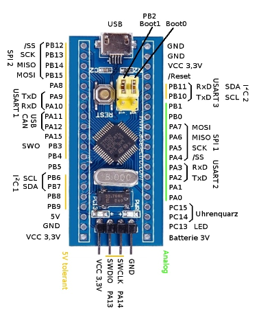
STM32-Blue Pill Pinout
The ARM Cortex M3 STM32F103C8 Microcontroller is used in the Blue pill board. Unlike the name, “Blue Pill” the Microcontrollers name STM32F103C8T6 has a meaning behind it.
- STM » stands for the manufacturers name STMicroelectronics
- 32 » stands for 32-bit ARM architecture
- F103 » stands to indicate that the architecture ARM Cortex M3
- C » 48-pin
- 8 » 64KB Flash memory
- T » package type is LQFP
- 6 » operating temperature -40°C to +85°C
Now let us look into the specifications of this Microcontroller.
| Architecture | 32-bit ARM Cortex M3 |
| Operating Voltage | 2.7V to 3.6V |
| CPU Frequency | 72 MHz |
| Number of GPIO pins | 37 |
| Number of PWM pins | 12 |
| Analog input Pins | 10 (12-bit) |
| USART Peripherals | 3 |
| I2C Peripherals | 2 |
| SPI Peripherals | 2 |
| Can 2.0 Peripheral | 1 |
| Timers | 3(16-bit), 1 (PWM) |
| Flash Memory | 64KB |
| RAM | 20kB |
PROGRAMMING WITH ARDUINO IDE
In order to program STM32F103C8T6 board with Arduino IDE we need a USB to TTL CP2102 converter.
Connection Diagram
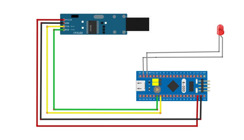
Connect 5V and Gnd pin in TTL to the Vcc and Gnd pins in STM-32. Also connect the RX pin of TTL to A9 pin of STM-32 (which is the TX pin in STM-32) and TX pin of TTL to A10 pin of STM-32 (which is the RX pin in STM-32). Also do the connections of led as in the circuit diagram.
Now let us upload the blink sketch to the STM-32 board.
For uploading the program
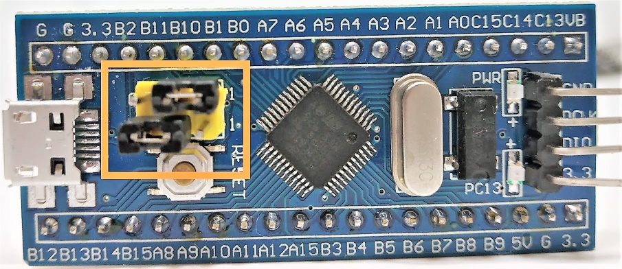
STM-32 have two boot pins (boot0 and boot1) whose values can be changed by shorting numbers and switch the board between programming and operating mode. In order to upload the sketch we must turn the boot0 pin high and boot1 should be grounded (boot1 is always grounded) as in the below figure.
Open the Arduino IDE and follow the below procedures to add the STM-32 board to the IDE and do the LED blinking project.
1. Go to File → Preferences →In the additional Boards Manager URL text box paste the below link: http://dan.drown.org/stm32duino/package_STM32duino_index.json

2. Now go to Tools → Boards →Board Manager

3. Now search for STM32 and Install STM32F1xx board.

4. After installing the board ,we can open and upload example program (blink) for STM32.
Select Tools→ Board→ Select STM32F103C Series. Then Select the COM port in which the board is connected.

Select Upload method→ Serial

Compile and upload the code

Sample code:
void setup() {
// initialize digital pin PB1 as an output
pinMode(PB1, OUTPUT);
}
void loop() {
digitalWrite (PB1, HIGH); // turn the LED on by making the voltage HIGH
delay(1000); // wait for a second
digitalWrite (PB1, LOW); // turn the LED off by making the voltage LOW
delay(1000); // wait for a second
}
5. After Done Uploading, you can see the LED Blinking.
Since the programming part is over we must change the programming mode to operational mode by grounding the boot0 and boot1 pins as in the below figure.

And that’s it, our LED blinking project is ready !!!


