


Raspberry Pi Pico is Raspberry Pi's first microcontroller board, designed especially for physical computing. It can be easily reprogrammed over USB from a Raspberry Pi or other computer using the C/C++ SDK or the official MicroPython port.
Raspberry Pi Pico is a low-cost, high-performance microcontroller board with flexible digital interfaces.
Board Specifications
- RP2040 microcontroller chip designed by Raspberry Pi in the United Kingdom
- Dual-core ARM Cortex M0+ processor, flexible clock running up to 133 MHz
- 264kB of SRAM, and 2MB of on-board Flash memory
- Castellated module allows soldering direct to carrier boards
- USB 1.1 Host and Device support
- Low-power sleep and dormant modes
- Drag & drop programming using mass storage over USB
- 26 multi-function GPIO pins
- 2×SPI, 2×I2C, 2×UART, 3×12-bit ADC, 16×controllable PWM channels
- Accurate clock and timer on-chip
- Temperature sensor
- Accelerated floating point libraries on-chip
- 8×Programmable IO (PIO) state machines for custom peripheral support
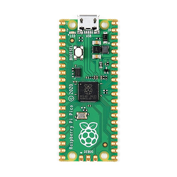
GPIO Pinout & Description

- 26 × multi-function 3.3V GPIO pins
- 2 × SPI, 2 × I2C, 2 × UART, 3 × 12-bit ADC, 16 × controllable PWM channels
- 8 × Programmable I/O (PIO) state machines for custom peripheral support.
- Castellated module allows soldering directly to carrier boards.
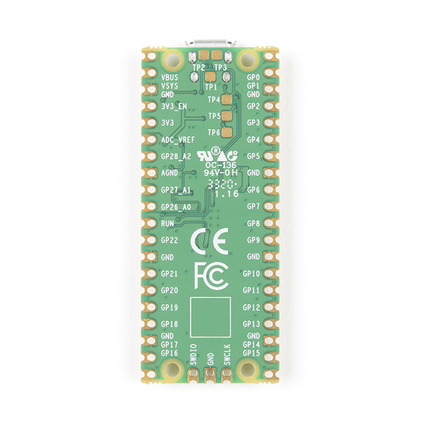
Operating at 3.3V, the Raspberry Pi Pico has a 40 pin GPIO, but it does not share the same form factor as the Raspberry Pis before it. It is having GPIO pins for digital inputs / outputs, pulse width modulation (PWM) and for specialist communication protocols such as I2C, SPI, UART/Serial. The GPIO also has three Analog inputs, that use variable voltages to connect to, for example, a potentiometers, joystick or light-dependent resistor.
Pinout Description
1. It supports four 12-bit SAR based analog to digital converters. But only three analog channels are exposed to pinout. The fourth analog channel is internal connected to the internal temperature sensor. Therefore, if we want to measure temperature, we can directly use build-in temperature by reading the analog value of ADC4.
2. RP2040 chip has two I2C controllers. Both I2C controllers are accessible through GPIO pins of Raspberry Pi Pico
I2C controller of RP4020 chip supports following features:
- Master or Slave Mode ( Default salve address = 0x055)
- Three speed modes such as Standard ( m 0 to 100 Kb/s) , Fast( less than or equal to 400 Kb/s) and Fast Plus mode ( less than or equal to 1000 Kb/s)
- Transmit and Receive Buffers
- Can be used in interrupt and DMA mode
3. RP2040 chip supports two SPI peripherals. Both SPI module pins are accessible through GPIO pins of Raspberry Pi Pico.
Each SPI controller supports master and slave mode and are compatible with following four modes:
- Motorola SPI Interface
- TI Serial Interface
- National Semiconductor Serial Interface
It has 8 buffers for each transmitter and receiver of SPI controller. Moreover, it can also be driver with interrupt or DMA.
4. RP2040 contains two identical UART peripherals with separate 32×8 Tx and 32×12 Rx FIFOs.
Some of the prominent features of UART peripherals are:
- Programmable Baud rate generator
- Supports standard asynchronous communication bits such as start, stop and parity bit
- Programmable hardware serial flow control
5. RP2040 microcontroller contains 8 PWM blocks and each PWM block provides two PWM signals. That means each slice can drive up to two PWM signals. Hence, there is a total of 16 PWM signal output available on Raspberry Pi Pico.
Programming in Pico board
Raspberry Pi foundation provided two programming options to write programs for Raspberry Pi Pico board such as C/C++ SDK and MicroPython. They also provide their own SDks for both C and MicroPython.
- Pico C/C++ SDK
- Pico Python SDK
How to Set Up the Raspberry Pi Pico
If you want to setup MicroPython in Pico board follow the steps below:
1. Download the MicroPython UF2 file from the MicroPython tab.
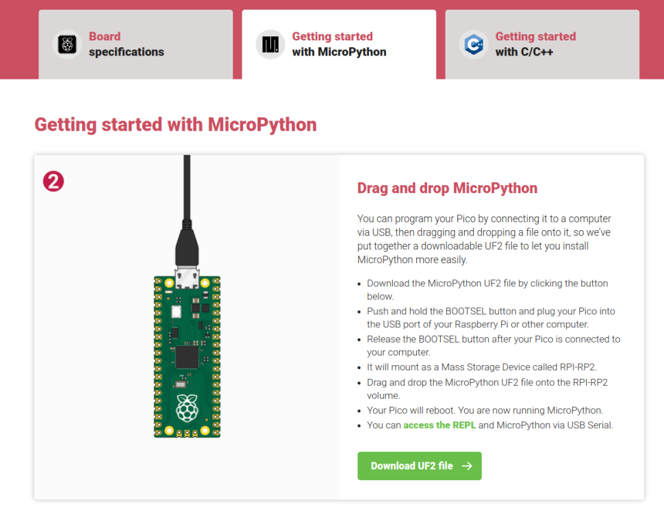
2. Push and hold the BOOTSEL button on the Pico, then connect to your computer using a micro USB cable. Release BOOTSEL once the drive RPI-RP2 appears on your computer.
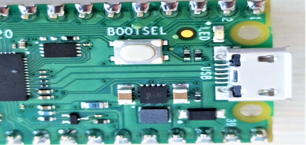
3. Drag and drop the UF2 file on to the RPI-RP2 drive. The Raspberry Pi Pico will reboot and will now run MicroPython.
Note:-Similarly you can flash any code in to the board using UF2 files.
If you want to setup Thonny IDE in Pico board follow the steps below:
1. Download and install Thonny for your OS, if you don’t already have it. You can grab it for free from the Thonny website.
2. In a web browser, download the required backend for Thonny to communicate with the Raspberry Pi Pico.
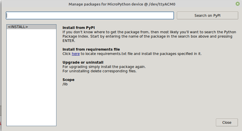
3. In Thonny, go to Tools > Manage Packages and select Install from local file. Navigate to where the file has been downloaded and select the file to install. When done restart Thonny.
Note:-When you connect the Pico board to the computer, you must push and hold the BOOTSEL button on the Pico. Release BOOTSEL once the drive RPI-RP2 appears on your computer.
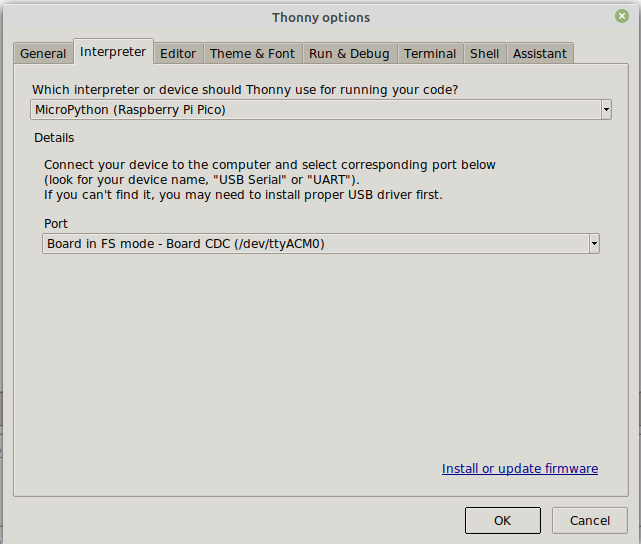
4. Connect the Raspberry Pi Pico to your computer using micro USB cable. In Thonny, go to Tools > Options and click on the Interpreter tab. From the interpreter dropdown list select MicroPython (Raspberry Pi Pico). The port dropdown menu can be left to automatically detect the Pico or you can directly select the port that appears in that tab. Click Ok to close.
The Python Shell will now update to show that the Pico is connected and working.
5. To test, we can print a function “hello world” in the python shell. Press enter to run the code.

Interfacing RGB Led module with Pico board
Let’s have a look at how to blink RGB led module in Pico board.
Connection
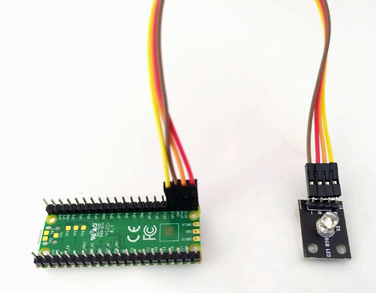
1. Connect the GPIO pins of Pico board with RGB pins of led module.
Here we have connected GPIO13, GPIO14, GPIO15 to the B,G,R of led module. GND is connected with GND of led module.
2. Connect the Pico board with the computer using micro USB cable.
Note:-When you connect the Pico board to the computer, you must push and hold the BOOTSEL button on the Pico. Release BOOTSEL once the drive RPI-RP2 appears on your computer.
3. In Thonny IDE, go to Tools > Options and click on the Interpreter tab. From the interpreter dropdown list select MicroPython (Raspberry Pi Pico). The port dropdown menu can be left to automatically detect the Pico or you can directly select the port that appears in that tab. Click Ok to close.
4. The code is given in the below Github link:
https://github.com/elementzonline/RaspberryPi-Pico-Samplecodes/blob/main/RGB_led.py
Run the code, the RGB led starts blinking .
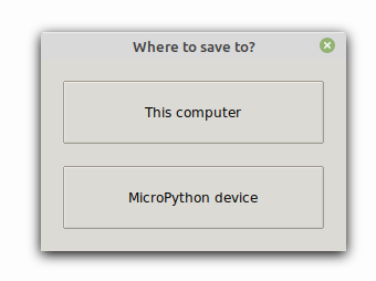
When you run the code , it will ask where to save the code. You can save either in the computer or in the MicroPython device.
Save the code as main.py so even if we reconnect the board or if we are giving power using a 5v 2A adapter without connecting to the pc, the code will run automatically, here the led blinks automatically.


