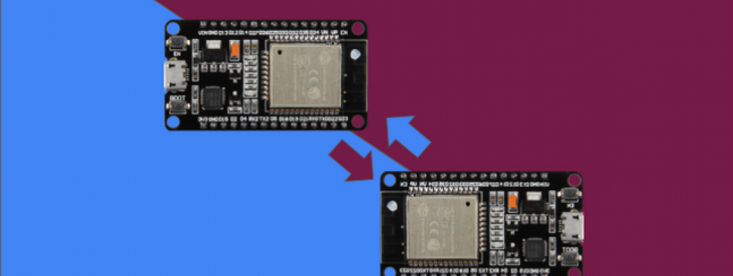
Welcome to a new tutorial on Google Cloud Platform and ESP32. In this blog we are establishing a device to device communication via GCP. The system consists of two ESP32 boards of which one has a relay board connected to it which is toggled using the in-built button of the other board. 


PINOUT


We will be using the built-in push button of the ESP32 module for this tutorial with a Relay module getting toggled along with the button.


HARDWARE CONNECTION


ESP32

Relay Board

Vin/5V

5V

GND

GND

D13

IN


A 5V relay is used here and hence, assuming that a sufficient power supply is given to the ESP32 module, the relay is directly connected to the Vin of the module.


The second ESP32 board has no external peripherals connected as only the built-in button is used in this tutorial.


GOOGLE IOT CORE ESP32 SETUP


Follow the previous blog for set up instructions. The link is given below:


https://www.elementzonline.com/blog/Connecting-ESP32-to-Google-Cloud-IoT


If you have already completed the setup, you can continue to the next step.


WRITING THE CLOUD FUNCTION


  • First open the GCP console

  • Now, navigate to the Cloud Functions page. (You can use the search tool)

  • Click the Create Function button.

  • Now fill in a preferred function name (Eg: relaycloudiot) and your region (Eg: europe-west1). Select the trigger type as Cloud Pub/Sub and then select the topic to which your devices were added during the setup.


  • Click save and proceed to the next step of uploading the code.

  • A new window will appear. Select the Runtime as Node.js 10 and Entry Point as recvMsg 


  • Select the index.js file and paste the below code into the editor.


'use strict';
const {google} = require('googleapis');

const projectId = 'YOUR_PROJECT_ID';
const cloudRegion = 'YOUR_REGION'; //eg: europe-west1

exports.recvMsg = function (event, callback) {
  console.log(event.data);
  const record = JSON.parse(
    event.data
      ? Buffer.from(event.data, 'base64').toString()
      : '{}');
  console.log(record);

  const config = {
    cloudRegion: record.cloudRegion,
    deviceId: record.deviceId,
    registryId: record.registryId,
    toggle: record.toggle
  };
  google.auth.getClient().then(client => {
    google.options({
      auth: client
    });
    console.log('START setDeviceConfig');
    const parentName = `projects/${projectId}/locations/${cloudRegion}`;
    const registryName = `${parentName}/registries/${config.registryId}`;
    const binaryData = Buffer.from(JSON.stringify(config)).toString('base64');
    const request = {
      name: `${registryName}/devices/${config.deviceId}`,
      versionToUpdate: 0,
      binaryData: binaryData
    };
    console.log(registryName);
    console.log('Set device config.');
    return google.cloudiot('v1').projects.locations.registries.devices.modifyCloudToDeviceConfig(request);
  }).then(result => {
    console.log(result);
    console.log(result.data);
  });
};


  • Now select the package.json file and paste the code below into the editor.


{
  "name": "relaycloudiot",
  "version": "0.0.1",
  "description": "Script for device to device communication",
  "main": "index.js",
  "license": "Apache-2.0",
  "dependencies": {
    "googleapis": ">=32.0.0"
  }
}


  • Finally use the deploy button to deploy your function


  • Wait till the green tick mark appears.


TRANSMITTER ESP32 SETUP


  • Use the Mongoose OS Tool to upload the code below to the ESP32 module.


To know how visit the previous blog:


https://www.elementzonline.com/blog/Connecting-ESP32-to-Google-Cloud-IoT


load('api_timer.js');
load('api_dht.js');
load('api_config.js');
load('api_mqtt.js');
load('api_sys.js');
load('api_gpio.js')

// GPIO pin which has the built-in LED connected
let btn = Cfg.get('board.btn1.pin');
//Set the telemetry topic
let topic = '/devices/' + Cfg.get('device.id') + '/events';

GPIO.set_mode(btn, GPIO.MODE_INPUT);

let payload = {
cloudRegion: 'YOUR_REGION', //europe-west1
deviceID: 'DEVICE_ID_OF_RECEIVER_ESP32',
registryId: 'YOUR_REGISTRY', // eg. mongiot-registry
toggle: 0
};

// This button handler will trigger function when button is released, with a 200 ms debounce time:
GPIO.set_button_handler(btn, GPIO.PULL_DOWN, GPIO.INT_EDGE_NEG, 100, function(x) {
  payload.toggle = !payload.toggle;
  // The state we'll publish is the epoch time (in JSON) the button was pushed and released:
  let msg = JSON.stringify(payload);
  // Publish message with a QoS 1
  // MQTT.pub() returns 1 in case of success, 0 otherwise.
  let ok = MQTT.pub(topic, msg, 1);
  print("Button: ", payload.toggle ? "ON" : "OFF");
}, null);


  • On successful upload, you should be able to start seeing button at the Serial Console of the MOS Tool.


RECEIVER ESP32 SETUP


  • Use the Mongoose OS Tool to upload the code below to the ESP32 module with the Relay board connected. [P.S. Select the correct COM Port for the ESP32 module, if both the modules are connected to the same PC.]


load('api_timer.js');
load('api_dht.js');
load('api_config.js');
load('api_mqtt.js');
load('api_sys.js');
load('api_gpio.js')

// GPIO pin which has the built-in LED connected
let relay = 13;
let topic = '/devices/' + Cfg.get('device.id') + '/config';

GPIO.set_mode(relay, GPIO.MODE_OUTPUT);
GPIO.write(relay, 0);

MQTT.sub(topic, function(conn, topic, msg) {
  // print('Topic:', topic, 'message:', msg);
  let relay_state = JSON.parse(msg).toggle || 0;
  print("Relay: ", relay_state ? "ON" : "OFF");
  GPIO.write(relay, relay_state);
}, null);


  • If everything was set up correctly, you should be able to toggle the relay connected at the receiver ESP32 module with the in-built button of the transmitter ESP32 module.

  • You can use the serial console of mongoose to verify the same.